What Are Transformer Windings?
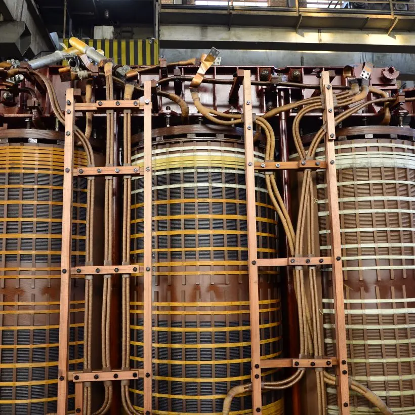
Transformer windings are coils of insulated conductor — copper or aluminium — wound around a laminated steel core. They are the components that actually perform the job of voltage transformation. Without windings, a transformer is just a tank full of oil and a block of steel.
Every transformer has at least two sets of windings: the primary winding and the secondary winding. The primary winding receives electrical energy at the input voltage. This current flowing through the primary creates a magnetic flux in the steel core. That alternating magnetic flux, in turn, induces a voltage in the secondary winding — and this is the output voltage that powers your factory, building, or equipment.
The ratio of turns (number of loops) between the primary and secondary windings determines the voltage ratio. A step-down distribution transformer in Pakistan, for example, might have an 11,000 V primary and a 400 V secondary — the primary has far more turns of finer conductor, while the secondary has fewer turns of thicker conductor to handle the higher current at lower voltage.
Copper vs Aluminium Conductors
The two conductor materials used in transformer windings are copper and aluminium. Copper has been the traditional choice for decades due to its superior electrical conductivity — approximately 60% higher than aluminium. This means copper windings can be physically smaller for the same current-carrying capacity, resulting in a more compact transformer with lower losses.
Aluminium windings are lighter and less expensive per kilogram, which makes them attractive for budget-conscious applications. However, aluminium conductors must be larger in cross-section to carry the same current as copper, which increases the overall winding size. We compare these two materials in detail in the copper vs aluminium section below.
Insulation Between Turns and Layers
The insulation system is just as critical as the conductor itself. Each turn of conductor is individually insulated — typically with enamel coating, paper wrapping, or a combination of both. Between layers of windings, additional insulation barriers (pressboard spacers, kraft paper, or Nomex sheets) prevent electrical breakdown between adjacent layers that operate at different voltages.
In oil-filled transformers — which account for the vast majority of distribution and power transformers in Pakistan — the entire winding assembly is submerged in transformer oil. The oil serves a dual purpose: it acts as an additional insulating medium and it carries heat away from the windings to the radiators for cooling. When oil quality degrades through moisture absorption or chemical contamination, the insulation system is compromised, and winding failures become far more likely.
How Windings Create Magnetic Coupling
The fundamental operating principle is electromagnetic induction. When alternating current flows through the primary winding, it generates an alternating magnetic field. This field is concentrated and channelled through the laminated steel core — the core acts as a magnetic highway, efficiently carrying the flux from the primary to the secondary winding with minimal leakage.
The secondary winding, linked by this same magnetic flux, has a voltage induced across its terminals proportional to its number of turns relative to the primary. The tighter the magnetic coupling between primary and secondary — meaning the less flux that leaks into the surrounding air instead of staying in the core — the more efficient the transformer. Winding geometry and placement on the core are carefully designed to maximise this coupling, which is why different winding configurations exist for different applications.
Core Type vs Shell Type Construction
The two fundamental transformer construction types are defined by the physical relationship between the core and the windings. Understanding this distinction matters because it affects repairability, short-circuit withstand capability, cooling efficiency, and suitability for different applications.
Core Type Transformer
In a core type transformer, the windings surround the core limbs. The laminated steel core typically forms a rectangular frame with two vertical limbs, and the primary and secondary windings are wound concentrically around each limb — the low-voltage (LV) winding sits closest to the core, and the high-voltage (HV) winding is wound over it on the outside.
Core type construction is the dominant design for distribution transformers in Pakistan. When you see a standard 100 KVA, 250 KVA, 500 KVA, or 1000 KVA distribution transformer on a pole or pad mount anywhere in Pakistan, it is almost certainly a core type unit. The reasons for this dominance are practical: core type transformers are easier to manufacture, easier to insulate (since the windings are on the outside and accessible), and critically, easier to repair and rewind. When a winding fails, a technician can remove and replace the coils without disassembling the core itself.
The main limitation of core type construction is that the windings are more exposed to mechanical forces during short-circuit events. Because the windings are on the outside, they experience significant radial and axial forces when a downstream short circuit drives massive fault currents through the transformer. In severe cases, these forces can deform or displace the windings.
Shell Type Transformer
In a shell type transformer, the core surrounds the windings. The laminated steel core forms a three-limbed structure (or more complex shapes), and the windings are sandwiched between the core sections. The core effectively wraps around and encloses the winding assembly.
Shell type construction offers several advantages for demanding applications. The surrounding core provides natural mechanical bracing for the windings, giving the unit significantly better short-circuit withstand strength. The windings are also better shielded from external mechanical damage. Additionally, the shell type design typically provides better magnetic coupling (lower leakage flux) because the core more completely encloses the magnetic path.
Shell type transformers are predominantly used in larger power transformers (above 5 MVA), special-purpose transformers, and applications where high short-circuit strength is essential — such as furnace transformers, traction transformers, and generator step-up units. They are less common in standard distribution applications because they are more complex and expensive to manufacture, and repairs are more difficult since accessing the windings requires partial disassembly of the core.
Comparison Table: Core Type vs Shell Type
| Factor | Core Type | Shell Type |
|---|---|---|
| Winding position | Windings surround the core | Core surrounds the windings |
| Common sizes | 25 KVA to 5000 KVA (distribution) | 5 MVA and above (power) |
| Use in Pakistan | Most distribution transformers | Large power & special-purpose units |
| Short-circuit strength | Moderate — windings exposed to forces | High — core braces the windings |
| Cooling | Good — windings exposed to oil flow | Requires directed oil flow channels |
| Repairability | Easy — coils removable from core | Difficult — core must be partially disassembled |
| Manufacturing | Simpler and less expensive | Complex and more expensive |
| Magnetic leakage | Moderate | Low — core encloses the flux path |
| Weight | Lighter for equivalent rating | Heavier due to additional core material |
| Best for | Distribution, general industrial | Power stations, furnaces, traction |
Winding Configurations
Within the core type and shell type frameworks, several specific winding configurations are used depending on the voltage class, current rating, and application requirements. Each configuration offers different trade-offs in terms of insulation stress, cooling efficiency, mechanical strength, and manufacturing complexity.
Concentric Windings
Concentric windings are the most common configuration in core type distribution transformers. The LV (low-voltage) winding is wound directly on the core limb first, and the HV (high-voltage) winding is wound concentrically over it, separated by an insulating cylinder or duct.
The LV winding goes on the inside for two practical reasons. First, the LV winding operates at lower voltage, so less insulation is needed between it and the grounded core. Second, the LV winding carries higher current (at lower voltage), so placing it closer to the core keeps the mean turn length shorter, reducing conductor material and resistive losses.
The insulating duct between the LV and HV windings serves a dual purpose — it provides the necessary dielectric clearance and it creates a channel for oil circulation, which helps cool the windings from the inside out. Nearly every distribution transformer you will encounter across Pakistan — whether it is a 25 KVA pole-mounted unit serving a village or a 2000 KVA pad-mounted unit powering a textile mill — uses concentric winding construction.
Sandwich (Interleaved) Windings
In sandwich or interleaved winding configuration, the HV and LV windings are divided into multiple sections and arranged alternately along the core limb — like layers in a sandwich. Instead of one continuous HV coil over one continuous LV coil, you get alternating HV-LV-HV-LV sections stacked vertically.
This configuration is primarily used in shell type transformers. The key advantage is that the interleaving significantly reduces leakage reactance — the voltage drop that occurs under load due to magnetic flux that does not fully link both windings. Low leakage reactance means better voltage regulation, which is important for applications with rapidly varying loads.
Sandwich windings also distribute the voltage stress more evenly across the winding height and improve the impulse voltage distribution (how a lightning surge or switching transient distributes across the winding turns). This makes the configuration well-suited for transformers in areas prone to lightning or on systems with frequent switching operations.
Disc Windings for HV Applications
Disc windings (also called disc-type or continuous disc windings) are used for high-voltage windings, particularly in transformers rated 33 kV and above. In this configuration, the conductor is wound in flat disc-shaped coils (each consisting of multiple turns), and these discs are stacked vertically along the core limb with spacers between them.
The spacers between discs create horizontal oil ducts that allow transformer oil to circulate through and between the discs, providing excellent cooling. This is critical for HV windings because they carry high voltage across many turns, generating significant heat that must be efficiently removed.
Disc windings also handle impulse voltages well. The capacitance distribution in a properly designed disc winding ensures that voltage surges from lightning or switching are distributed more uniformly across the winding, rather than concentrating dangerously at the line-end turns. For transformers serving areas of Pakistan with frequent thunderstorm activity or connected to overhead lines, disc-wound HV coils provide an important layer of protection.
Helical Windings for LV High-Current
Helical windings (also called spiral windings) are used for LV windings that must carry very high currents — typically in transformers rated 500 KVA and above. In this configuration, the conductor (often multiple parallel strips of copper or aluminium) is wound in a single-layer helix along the core limb, like a large spring or coil.
Because the LV winding of a large transformer carries hundreds or even thousands of amperes, the conductor cross-section must be very large. A helical winding accommodates this by using wide, flat conductor strips wound side by side. The single-layer design means every turn is exposed to oil on both sides, which provides excellent cooling — essential when dealing with the high I2R losses generated by very heavy currents.
Helical windings are mechanically robust because the wide, flat conductors are inherently resistant to the radial forces generated during short-circuit events. This makes them particularly suitable for industrial transformers that may experience frequent motor starting surges or other high-inrush events. At TransfoLine, we regularly work on large distribution and power transformers with helical LV windings during repair and rewinding operations.
Common Winding Failures
Winding failures are among the most serious transformer faults. Unlike an oil leak or a corroded bushing that can be repaired relatively quickly on site, a winding fault almost always means the transformer must be taken out of service, transported to a workshop, and either rewound or replaced. Understanding these failure modes helps you recognise problems early and take preventive action.
1. Turn-to-Turn Short Circuit
A turn-to-turn short occurs when the insulation between two adjacent turns of conductor breaks down, allowing current to flow directly from one turn to the next instead of following the full winding path. This creates a shorted loop that acts like a low-impedance secondary winding — it draws heavy circulating current, generates intense localised heat, and rapidly destroys the surrounding insulation.
Turn-to-turn shorts are the most common and most insidious winding fault. In the early stages, they may cause only a slight increase in winding temperature and a subtle change in the transformer's electrical characteristics. If not detected, they progressively burn through more insulation, involving more turns and eventually escalating to a layer-to-layer fault or a winding-to-ground fault.
Common causes include insulation ageing from prolonged overheating, moisture ingress that degrades insulation dielectric strength, voltage surges from lightning or switching, and manufacturing defects such as insufficient insulation between turns. Dissolved gas analysis (DGA) of the transformer oil can detect turn-to-turn shorts early — elevated hydrogen and acetylene levels are characteristic signatures.
2. Layer-to-Layer Fault
A layer-to-layer fault occurs when the insulation barrier between two adjacent layers of windings fails. Since the voltage difference between layers is significantly higher than between individual turns, a layer-to-layer fault releases more energy and causes more extensive damage than a turn-to-turn short.
These faults often develop from an undetected turn-to-turn short that has been progressively degrading the surrounding insulation. They can also result from moisture contamination of the inter-layer insulation, mechanical displacement of winding layers during a short-circuit event, or degradation of the insulating paper or pressboard barriers.
A layer-to-layer fault typically produces a noticeable change in the transformer's impedance and no-load current, and it generates significant quantities of dissolved gases in the oil. If the transformer has a Buchholz relay, a layer-to-layer fault will usually produce enough gas to trigger an alarm or trip.
3. Winding-to-Ground Fault
A winding-to-ground fault occurs when the insulation between a winding and the grounded core (or tank) fails completely, allowing current to flow from the winding conductor to ground. This is the most severe winding fault — it creates a dead short circuit that typically trips protective devices immediately and can cause explosive damage if fault current is high enough.
Winding-to-ground faults are often the terminal stage of a progressive insulation failure that began as a turn-to-turn or layer-to-layer fault. They can also result from severe mechanical damage during an external short circuit, catastrophic insulation failure from moisture or contamination, or a foreign object (such as a broken conductor fragment or debris) bridging the gap between winding and core.
After a winding-to-ground fault, the transformer invariably requires rewinding. The key question is whether the core has also been damaged — if the core laminations are fused or burned, the repair becomes significantly more complex and expensive.
4. Open Circuit (Broken Conductor)
An open circuit occurs when a winding conductor physically breaks, completely interrupting the current path. In a primary winding, this means the transformer stops working entirely — no current flows, no flux is generated, no voltage appears on the secondary. In a secondary winding, it means one or more phases lose output.
Conductor breaks can result from manufacturing defects (a weak joint or cold solder point that fails under thermal cycling), fatigue from repeated mechanical stress during short-circuit events, or corrosion of the conductor at a point where moisture has penetrated the insulation. Open circuits are less common than short-circuit faults but are equally disabling.
5. Winding Deformation from Short-Circuit Forces
When a short circuit occurs on the load side of a transformer, fault currents many times the normal rated current flow through the windings. These massive currents generate enormous electromagnetic forces — axial forces that try to crush or stretch the windings vertically, and radial forces that try to expand the outer (HV) winding and compress the inner (LV) winding.
If these forces exceed the mechanical strength of the winding structure, the windings deform — coils bulge, shift, tilt, or collapse. Even if the insulation survives the initial event, the mechanical displacement changes the spacing between conductors, creating points of reduced insulation clearance that will fail under subsequent normal voltage stress.
Winding deformation is a particular risk for older transformers where the insulation materials have lost their mechanical resilience due to ageing, and for transformers that have experienced multiple short-circuit events. Frequency Response Analysis (FRA) testing is the most sensitive diagnostic method for detecting winding deformation before it progresses to an electrical fault.
Warning Signs of Winding Problems
Winding failures rarely happen without warning. The challenge is recognising the warning signs early enough to take action before a minor developing fault becomes a catastrophic failure. Here are the key indicators that your transformer's windings may be in trouble.
Increased Winding Temperature
If winding temperature rises under the same load conditions that previously produced lower temperatures, something has changed inside the transformer. A developing turn-to-turn short generates localised heating. Increased winding resistance from conductor degradation or loose connections also produces additional heat. Monitor winding temperature indicators and compare against historical baselines — a sustained upward trend is a red flag.
Change in No-Load Current
The no-load current (measured when the transformer is energised but carrying no load) should remain stable over the life of the transformer. A significant change in no-load current — either an increase or an alteration in the harmonic content — can indicate shorted turns in the winding or changes in the core's magnetic circuit caused by winding displacement. This is one of the simplest and most revealing tests a technician can perform.
Dissolved Gas Analysis (DGA) Indicators
Transformer oil testing through DGA is the most powerful diagnostic tool for detecting developing winding faults. Specific gases indicate specific fault types:
- Hydrogen (H2) — indicates partial discharge or low-energy arcing in the insulation, often the earliest sign of a developing turn-to-turn fault
- Carbon monoxide (CO) and carbon dioxide (CO2) — indicate overheating or degradation of cellulose insulation (the paper wrapping around the winding conductors). Elevated CO is a warning that the winding insulation is being thermally degraded
- Acetylene (C2H2) — indicates high-energy arcing, which means a serious fault is present or developing. Any detectable acetylene requires immediate investigation
- Ethylene (C2H4) — indicates severe overheating of oil, potentially from a hot spot in the windings
Regular DGA testing — at least annually for critical transformers, and after any unusual event — is the single most effective maintenance practice for catching winding problems before they cause failures.
Increased Impedance
A transformer's impedance (measured as a percentage) should remain consistent throughout its operating life. If routine testing reveals a change in impedance — particularly an increase — it may indicate winding deformation from a past short-circuit event. Even a 2-3% change from the factory-measured value warrants investigation, as it suggests the winding geometry has been altered.
Unusual Humming or Vibration
All transformers hum — the 100 Hz vibration from magnetostriction in the core is normal. But a change in the character of the hum — louder, with new harmonics, or accompanied by rattling or buzzing — can indicate loose windings, displaced coils, or a turn-to-turn short that is creating abnormal magnetic flux patterns. If your transformer starts sounding different, do not ignore it. Have it inspected.
Buchholz Relay Trips
The Buchholz relay is a gas-actuated protective device fitted in the pipe between the transformer tank and the conservator. When a winding fault decomposes oil or insulation, it produces gas bubbles that collect in the Buchholz relay. A slow accumulation of gas triggers an alarm; a sudden surge of gas (indicating a severe fault) triggers a trip that disconnects the transformer.
A Buchholz alarm should never be ignored or reset without investigation. Collect the trapped gas and have it analysed — the gas composition tells you what type of fault is occurring. If the relay has tripped (not just alarmed), do not re-energise the transformer until a technician has performed a thorough investigation including oil sampling, insulation resistance testing, and turns ratio measurement.
Rewinding — When and How
When a winding fault is confirmed, the transformer owner faces a critical decision: rewind or replace? In many cases, rewinding is the better choice — it restores the transformer to like-new electrical performance while retaining the existing tank, core, bushings, and accessories. But rewinding is not always viable, and the decision depends on several factors.
When Rewinding Is Viable
- The core is in good condition — if the laminated steel core has not been damaged by through-faults (burned spots, fused laminations, or excessive core loss), it can be reused. The core typically outlasts multiple sets of windings
- The tank is structurally sound — the tank must be free of major structural damage, excessive corrosion, or distortion that would compromise oil containment
- Replacement parts are available — bushings, tap changers, gaskets, and other spare parts needed for reassembly must be obtainable
- The KVA rating is still suitable — there is no point rewinding a 500 KVA transformer if your load has grown to 800 KVA. However, in some cases, a transformer can be rewound to a different KVA rating within the physical constraints of the existing core and tank
When Replacement Is Better
- Core is damaged beyond practical repair
- Tank integrity is compromised
- The transformer is very old and other components (bushings, tap changer, radiators) are also at end of life
- A different KVA rating, voltage class, or impedance is needed that exceeds the physical limits of the existing design
- The unit was already rewound previously and the core shows signs of fatigue
The Rewinding Process
At TransfoLine, our transformer rewinding process follows a rigorous sequence to ensure the rewound unit performs to original factory specifications — or better.
- Oil draining and disassembly — the transformer oil is drained, and the active part (core and winding assembly) is removed from the tank. Bushings, tap changer, and accessories are removed and inspected separately
- Stripping the old windings — the damaged windings are carefully removed from the core. During this process, the core is inspected for damage — burned spots, loose laminations, or signs of overheating
- Core cleaning and re-insulation — the core limbs are cleaned, any damaged insulation on the core is replaced, and the core is tested for ground insulation and inter-lamination insulation (core loss test)
- Winding new coils — new primary and secondary coils are wound using fresh copper or aluminium conductor (matching or upgrading the original specification). Insulation between turns, layers, and windings is applied according to the voltage class and insulation design
- Assembly — the new windings are assembled onto the core limbs, clamped, braced, and the leads are connected to the bushings and tap changer. Proper clamping pressure is critical to ensure the windings withstand short-circuit forces
- Vacuum drying — the complete core-and-winding assembly undergoes vacuum drying to remove all moisture from the insulation. This step is essential — even small amounts of trapped moisture drastically reduce insulation life
- Tank preparation and oil filling — the tank is cleaned, repainted if needed, fitted with new gaskets, and the active part is lowered back in. Fresh transformer oil is filled under vacuum to ensure no air pockets remain
- Testing and certification — the rewound transformer undergoes a complete suite of tests: turns ratio, insulation resistance (megger), winding resistance, no-load loss, load loss, impedance, and high-voltage withstand test. Only after passing all tests is the unit certified and released for delivery
Quality Checks After Rewinding
A properly rewound transformer should meet or exceed these benchmarks:
- Turns ratio within 0.5% of nameplate design value on all taps
- Insulation resistance above the minimum values specified for the voltage class (typically above 500 megohms for distribution transformers)
- No-load loss and load loss within the design specification
- Impedance within 10% of the original nameplate value
- High-voltage withstand test passed without breakdown or partial discharge
- Oil dielectric breakdown voltage above 40 kV (for mineral oil)
At TransfoLine, every rewound transformer ships with a comprehensive test report documenting all measurements. We stand behind our work with a warranty — if any winding-related fault develops within the warranty period, we repair it at no additional charge.
"Our 1500 KVA transformer failed during the monsoon season and we could not afford to wait weeks for a replacement. TransfoLine rewound it with copper conductors in 12 days. It has been running our flour mill flawlessly for two years now — even through peak summer loads. Their team was professional and the quality of work is excellent."
— Mill Owner, Flour Milling Group, Faisalabad
Copper vs Aluminium Windings
The choice between copper and aluminium windings is one of the most debated topics among transformer buyers in Pakistan. Both materials have legitimate applications, and the right choice depends on your specific requirements, operating conditions, and long-term priorities.
Comparison Table: Copper vs Aluminium
| Factor | Copper | Aluminium |
|---|---|---|
| Electrical conductivity | 100% (reference standard) | ~61% of copper |
| Weight (for same capacity) | Heavier | ~50% lighter |
| Conductor size (for same current) | Smaller cross-section | ~60% larger cross-section needed |
| Mechanical strength | Higher — better short-circuit withstand | Lower — more susceptible to deformation |
| Thermal conductivity | Higher — better heat dissipation | Lower |
| Material cost | Higher per kg | Lower per kg |
| Losses (I2R) | Lower (less resistance) | Higher (more resistance) |
| Lifespan | Longer — more durable joints and connections | Shorter — connections may loosen over time |
| Availability in Pakistan | Readily available | Readily available |
| Corrosion resistance | Excellent | Good, but oxidises at joints |
| Transformer size | More compact winding design | Larger winding requires bigger core and tank |
| Best for | Critical loads, high-utilisation, long life | Budget applications, lighter-duty loads |
When to Choose Copper
Copper windings are the superior choice for transformers that serve critical industrial loads, operate at high utilisation factors (consistently loaded above 60-70% of rated capacity), or are expected to remain in service for 25+ years. The lower resistive losses of copper windings translate into measurable energy savings over the transformer's lifetime — and in high-load, continuous-operation environments like textile mills, steel rolling mills, and chemical plants, these savings compound significantly.
Copper's higher mechanical strength also makes it the better choice for transformers exposed to frequent short-circuit events — such as those supplying motor-starting loads or operating on systems with high fault levels. The windings are better able to withstand the electromagnetic forces without deforming.
If you are purchasing a new transformer for a permanent installation with demanding loads, specify copper windings. The upfront premium is recovered through lower losses and longer service life.
When Aluminium Is Acceptable
Aluminium windings are a reasonable choice for lighter-duty applications, standby or backup transformers, temporary installations, and situations where initial capital conservation is the primary concern. A well-made aluminium-wound transformer, properly maintained, can provide reliable service for 15-20+ years in moderate-duty applications.
Aluminium's weight advantage also matters for pole-mounted distribution transformers where the structure must support the transformer weight, and for mobile or transportable transformer applications where lower weight simplifies handling and logistics.
The key consideration with aluminium is connection quality. Aluminium oxidises at connection points, and the oxide layer increases contact resistance, which generates heat and can cause joint failures over time. Proper connection techniques — using anti-oxidant compound, bi-metallic connectors at copper-to-aluminium transitions, and adequate torque — are essential for reliable long-term performance with aluminium windings.
Frequently Asked Questions
What causes transformer winding failure?
The most common causes are insulation degradation from heat and moisture, short-circuit forces that deform windings, voltage surges from lightning or switching, manufacturing defects, and long-term ageing. Poor maintenance — especially neglecting oil quality — accelerates insulation breakdown and leads to turn-to-turn or layer-to-layer faults. Sustained overloading is also a major contributor, as it generates excess heat that degrades the cellulose insulation wrapping the conductor.
Can a transformer be rewound?
Yes, most transformers can be rewound, provided the core is in good condition and the tank is structurally sound. The process involves stripping the old windings, re-insulating the core, winding new coils with fresh copper or aluminium conductor, vacuum drying, reassembly, and full electrical testing. TransfoLine provides professional rewinding services for transformers from 25 KVA to 8000 KVA across all major brands.
Which is better — copper or aluminium winding?
Copper is superior in conductivity (about 60% higher), mechanical strength, thermal performance, and longevity. Aluminium is lighter and less expensive upfront. For critical industrial loads with high utilisation, copper is the recommended choice. For lighter-duty or budget-conscious applications, aluminium provides adequate performance. The detailed comparison above covers all the factors.
How long do transformer windings last?
Transformer windings typically last 20-35 years with proper maintenance. The primary factor affecting winding life is the condition of the cellulose insulation, which degrades irreversibly with heat, moisture, and chemical contamination. Regular oil testing, maintaining proper cooling system function, avoiding sustained overloading, and keeping moisture out of the insulation system are the keys to maximising winding lifespan.
How do I know if my transformer needs rewinding?
Key indicators include consistently high winding temperatures, abnormal no-load or load losses, low insulation resistance readings (below the minimum for the voltage class), elevated dissolved gases (especially hydrogen and carbon monoxide) in oil analysis, Buchholz relay trips or alarms, and unusual humming or vibration. If multiple indicators are present, contact a qualified technician for a comprehensive diagnostic assessment before the issue escalates to an emergency.
What is the difference between core type and shell type transformer?
In a core type transformer, the windings surround the core limbs — the core is inside the windings. In a shell type transformer, the core surrounds the windings — the windings sit inside the core. Core type is more common in distribution transformers across Pakistan and is easier to repair and rewind. Shell type offers better short-circuit strength and is used in larger power transformers and critical applications such as furnace transformers and generator step-up units.
Winding problems? Get expert diagnosis.
Our engineers diagnose winding faults using DGA, insulation resistance testing, turns ratio measurement, and frequency response analysis. If rewinding is needed, we complete the job to factory specifications with full testing and warranty.
Request Winding Assessment →