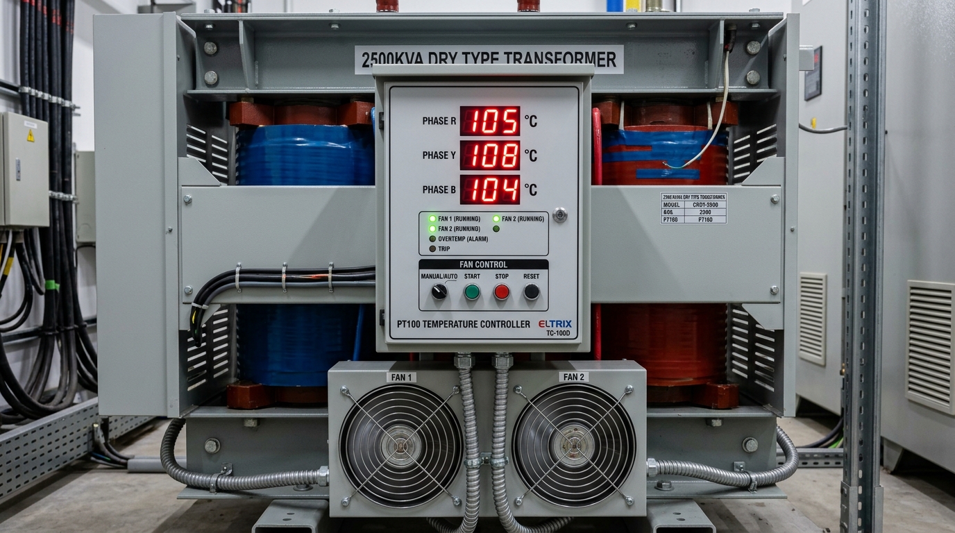
Direct Engineering Answer: Dry-type transformers rely on embedded PT100 RTD sensors inside the low-voltage winding hot spots to manage thermal dissipation. Digital microcontrollers automate cross-flow forced air (AF) cooling fans to boost capacity by up to 40% during peak building demand, triggering pre-alarms at 130°C and emergency VCB breaker trips at 150°C for Class F insulation.
1. Thermal Dynamics in Oil-Free Transformer Installations
In oil-immersed transformers, large volumes of circulating oil provide a massive thermal buffer, absorbing transient overload energy and distributing heat across external radiator banks. In stark contrast, Cast Resin Dry-Type Transformers operate with no liquid buffer; heat generated within the copper conductors must dissipate directly through the solid epoxy barrier into ambient air channels.
In Pakistani commercial basements and indoor plant rooms—where ambient summer temperatures regularly reach 40°C to 45°C and ventilation air changes may be constrained—precise, real-time thermal monitoring is the single most critical line of defense against premature insulation aging and catastrophic thermal runaway. Explore TransfoLine's dry-type transformer engineering hub for full system schematics.
2. Principle of Operation: Platinum RTD (PT100) Resistance Sensors
Temperature measurement in dry-type transformers is performed using PT100 Platinum Resistance Temperature Detectors (RTD) per DIN EN 60751. The operating principle relies on the highly linear and predictable positive temperature coefficient of pure platinum:
At 0°C, a PT100 sensor exhibits an electrical resistance of exactly 100.00 Ohms, increasing linearly to approx. 138.50 Ohms at 100°C and 157.30 Ohms at 150°C. Utilizing a 3-wire measurement circuit cancels out lead wire resistance errors across long cable runs from the transformer tank to the wall-mounted control panel.
3. Sensor Placement & Hot-Spot Mapping Inside LV Windings
Because the low-voltage (LV) winding carries the highest current density and is situated closest to the magnetic core iron, the thermal 'hot-spot' inevitably develops in the upper third of the LV coil assembly. TransfoLine embeds three dedicated PT100 sensors directly inside the LV winding ducts of Phase U, Phase V, and Phase W during factory assembly, with an optional fourth sensor attached to the magnetic core yoke to monitor iron losses.
4. Digital Microprocessor Controller Architecture & Programming
The PT100 signals feed into a specialized front-panel digital temperature controller (e.g. TEC System / TransfoLine T-154 series). The microcontroller continuously scans all channels, displays the highest phase temperature on a high-visibility LED readout, stores peak historical temperature logs, and actuates dedicated dry-contact output relays.
5. Standard Temperature Setpoints for Class F and Class H Insulation
The digital controller is configured with progressive four-stage threshold setpoints depending on the transformer insulation class:
| Control Function Relay | Class F Insulation (155°C Rating) | Class H Insulation (180°C Rating) | Automated Engineering Action |
|---|---|---|---|
| Fan Start (AF Mode) | 100°C | 120°C | Starts cross-flow forced cooling fans automatically. |
| Fan Stop (AN Mode) | 80°C | 100°C | Turns off cooling fans once windings cool down. |
| High Temperature Alarm | 130°C | 150°C | Activates BMS audiovisual alarm & control room beacon. |
| Over-Temperature Trip | 150°C | 170°C | Instantly trips 11kV VCB breaker to protect coils. |
6. Cross-Flow Forced Air (AF) Blowers & +40% Dynamic Overload
When high ambient heat or peak building electrical loads push winding temperatures above 100°C, the controller activates low-noise cross-flow tangential blowers mounted at the base of the coils. Forced air flowing through internal vertical ducts enhances convective heat transfer, enabling a 1,000 kVA transformer to continuously deliver up to 1,400 kVA (1.4 MVA) without exceeding thermal limits.
7. Integration with Building Management Systems (BMS & RS-485 Modbus)
TransfoLine controllers come standard with an isolated RS-485 Modbus RTU serial interface, allowing building engineers to stream real-time winding temperatures, fan status, and trip event logs directly into centralized SCADA and Building Management Systems (BMS). Explore our testing and commissioning services for full automation setup.
8. Fan Speed Control & Acoustic Noise Optimization
Modern temperature controllers feature variable frequency or dual-speed fan control. During moderate thermal loading, fans operate at low speed (45 dBA) to maintain quiet building environments, ramping up to maximum RPM only when extreme summer heat or sudden emergency load transfers demand maximum cooling airflow.
9. Troubleshooting Sensor Faults (Open Circuit / Short Circuit / E-01)
If an RTD wire is disconnected or severed, the controller indicates an 'Open Circuit (F-OP)' alarm without causing a false transformer trip. If shorted, 'F-SH' is displayed. TransfoLine maintains complete spare controllers, PT100 sensor probes, and cross-flow fans for rapid dispatch.
10. TransfoLine Calibration, Spare Parts & Replacement Sensors
TransfoLine provides on-site calibration of temperature control units, supply of replacement PT100 sensors, and diagnostic verification of trip relay loops across Pakistan. Contact our automation team for technical support.
11. Step-by-Step Field Calibration & Testing Protocol for PT100 Controllers
During routine maintenance or annual turnaround audits, TransfoLine engineers follow a strict 5-step diagnostic procedure to verify temperature control loop integrity:
- Sensor Loop Resistance Verification: Disconnect the 3-wire RTD terminal blocks and measure individual lead resistance with a 4.5-digit calibrated multimeter to verify balanced resistance across conductors (< 0.2 Ω lead variance).
- Simulated Temperature Injection: Connect a precision RTD decade calibrator (e.g. Fluke 724) to the controller inputs and inject simulated temperatures of 50°C, 100°C, 130°C, and 150°C to verify display accuracy within ±0.5°C.
- Fan Control Relay Actuation: Verify that the Fan Start relay energizes at exactly 100°C and de-energizes when temperature drops back below 80°C.
- Alarm & Trip Relay Dry-Contact Switching: Test continuity across the Alarm (130°C) and Trip (150°C) output contacts, confirming auxiliary trip signal transmission to the 11kV vacuum circuit breaker (VCB) shunt trip coil.
- Modbus Telemetry Verification: Poll internal registers via RS-485 to confirm that the Building Management System (BMS) accurately receives real-time phase temperatures and trip status flags.
12. Thermal Modeling of Dry Transformer Windings Under Overload Cycles
Under transient peak overloads—such as evening commercial shopping hours or simultaneous chiller compressor starts—the internal temperature rise of a dry-type transformer follows exponential heating curves governed by thermal time constants (τ ≈ 45 to 60 minutes). The PT100 temperature controller tracks these rate-of-rise slopes (ΔT/Δt) in real time. If the temperature rise exceeds 1.5°C per minute, the controller initiates forced-air fan staging preemptively before hot-spot temperatures reach critical alarm limits.
Frequently Asked Questions
FAQ What does an E-01 error code mean on a dry transformer temperature controller?
E-01 or F-OP indicates an open-circuit fault in the PT100 sensor loop for that specific phase; check terminal screw tightness and wiring continuity.
FAQ Can forced air fans run continuously on a dry-type transformer?
While fans can run continuously, it is best to operate in automatic temperature-controlled mode to maximize fan bearing lifespan and reduce energy usage.
FAQ How do I test if a PT100 sensor is functioning accurately?
Disconnect the sensor leads and measure resistance with a precision multimeter; at 25°C room temperature, the resistance should read approximately 109.7 Ohms.
FAQ What voltage power supply is required for the digital temperature controller?
Standard controllers operate on universal 85V to 265V AC/DC auxiliary control power.
FAQ Can TransfoLine replace damaged temperature controllers on third-party transformers?
Yes, we retrofit and calibrate digital temperature controllers on Schneider, Siemens, ABB, and indigenous dry-type transformers.
Need Direct Technical Assistance or a Factory-Direct Quote?
TransfoLine supplies, installs, overhauls, and repairs heavy industrial transformers across Pakistan with nationwide 48-hour delivery, genuine WAPDA P-10 compliance, and 12-month full warranty.