
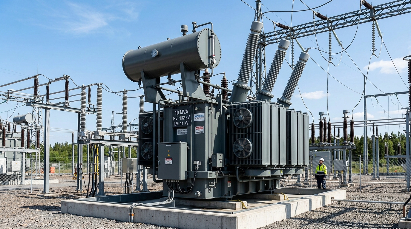
Direct Engineering Answer: Industrial facilities exceeding 1,500 kW connected load require high-voltage MVA power transformers (2.5 MVA to 20 MVA) connected to 11kV, 33kV, or 132kV dedicated feeders. Accurate sizing requires applying plant demand factors (0.70–0.85 in textile spinning), diversity factors (1.15–1.25), target power factor (0.95), and a 20% expansion allowance to prevent voltage dips during heavy motor starting.
1. The Strategic Transition from kVA Distribution to MVA Power Substation
As industrial manufacturing enterprises across Pakistan scale their production capacity—such as multi-unit composite textile spinning and weaving mills in Faisalabad, Multan, and Sheikhupura, steel re-rolling plants in Gujranwala and Lahore, sugar mills in Central Punjab and Sindh, and chemical synthesis complexes—their electrical energy demand rapidly outgrows the capacity of standard distribution transformers (which typically top out at 1,000 kVA / 1 MVA).
Attempting to power a multi-megawatt industrial complex by daisy-chaining multiple small distribution transformers on a congested 11kV utility line results in severe operational liabilities: crippling I2R line losses, heavy voltage drop during large induction motor starting, severe phase unbalance, and costly Maximum Demand Indicator (MDI) penalty surcharges from utility distribution companies like LESCO, FESCO, GEPCO, MEPCO, and K-Electric.
Transitioning to a dedicated high-voltage substation powered by a 2.5 MVA, 5.0 MVA, 10.0 MVA, or 20.0 MVA power transformer provides centralized, efficient, and robust power delivery. Operating at higher primary interconnection voltages (such as 33kV or 132kV dedicated grid lines) unlocks favorable utility bulk power tariffs (Tariff B3 and B4), delivering immediate operational savings that pay back substation capital costs within 2 to 3 years. Explore TransfoLine's complete range of high-voltage power transformers and custom substation engineering solutions.
2. Assessing Industrial Load Profiles: Continuous, Intermittent & Inrush
Accurate sizing of an MVA-class power transformer begins with a thorough electrical audit that categorizes all connected industrial machinery according to duty cycle and electrical behavior:
- Continuous Baseload (P_base): Heavy equipment running continuously 24 hours a day with constant power draw. In textile mills, this includes hundreds of spinning ring frames, continuous draw frames, carding machines, main air compressors, and central HVAC chillers. In chemical and food processing plants, baseload comprises continuous liquid circulation pumps, boilers, and refrigeration compressors.
- Cyclical / Intermittent Load (P_cyclical): Machinery that cycles between active and idle states during normal production batches. Examples include overhead gantry cranes, batch dyeing autoclaves, scrap metal balers, hydraulic stamping presses, and automated palletizers.
- Motor Starting Inrush Demand (P_inrush): Direct-On-Line (DOL) and Star-Delta starting of high-power medium-voltage and low-voltage induction motors (150 kW to 1,000 kW). During starting, induction motors draw 600% to 750% of rated full-load current for 3 to 15 seconds, creating transient electromagnetic flux depression and severe voltage sags across the primary transformer winding.
3. Step-by-Step Engineering Sizing Calculations for Multi-Megawatt Plants
To determine the optimal transformer MVA rating, electrical consulting engineers apply international standards (IEEE 399 / IEC 60076) using four critical electrical parameters:
- Total Connected Load (kW): The absolute arithmetic sum of all equipment nameplate ratings connected across the facility.
- Demand Factor (DF): The ratio of maximum simultaneous demand to total connected load. In textile plants, DF typically ranges between 0.75 and 0.85; in general light manufacturing, it ranges between 0.60 and 0.70.
- Diversity Factor (Div): Accounts for the statistical reality that different operational divisions (spinning, weaving, dyeing, administrative) do not peak simultaneously ($Div = 1.15 ext{ to } 1.30$).
- Operating Displacement Power Factor (cos phi): The plant power factor after reactive power compensation via an automatic PFI capacitor plant ($\cos \phi \ge 0.95$).
Base Apparent Power Demand (MVA) = Coincident Maximum Active Demand (MW) / Operating Power Factor (&cos; φ)
Recommended Transformer Rating (MVA) = Base Apparent Power (MVA) × 1.20 (Future Expansion Margin)
Comprehensive Worked Example: 60,000-Spindle Composite Textile Mill
Consider a new export-oriented spinning and yarn dyeing composite mill on Sheikhupura Road with a total connected load of 5,500 kW:
- Connected Load: 5,500 kW
- Plant Demand Factor: 0.82 → Peak Running Demand = $5,500 imes 0.82 = 4,510 ext{ kW}$
- Diversity Factor: 1.18 → Coincident Peak Active Demand = $4,510 / 1.18 = \mathbf{3,822 ext{ kW (3.82 MW)}}$
- Apparent Power Demand at 0.95 Power Factor: $S_{ ext{base}} = 3.822 ext{ MW} / 0.95 = \mathbf{4.023 ext{ MVA}}$
- Factoring 20% Expansion & Summer Thermal Margin: Design MVA = $4.023 imes 1.20 = \mathbf{4.83 ext{ MVA}}$
- Engineering Specification: Install a standard 5.0 MVA (5,000 kVA) 11kV/415V ONAN/ONAF Power Transformer equipped with motorized On-Load Tap Changer (OLTC).
4. Sector-by-Sector Capacity Planning Matrix (Textiles, Sugar, Cement, Steel)
The following engineering benchmark table outlines typical transformer capacities, primary voltages, and cooling classes across major industrial manufacturing sectors in Pakistan:
| Industrial Sector | Plant Scale / Capacity | Typical Connected Load | Standard Transformer Rating | Primary Grid Voltage |
|---|---|---|---|---|
| Textile Spinning Unit | 25,000 Spindles | 1,800 kW – 2,400 kW | 2.5 MVA – 3.15 MVA | 11 kV Dedicated Feeder |
| Composite Textile Mill | 50,000+ Spindles + Processing | 4,000 kW – 5,500 kW | 5.0 MVA (5,000 kVA) | 11 kV / 33 kV Grid |
| Steel Re-Rolling Mill | 200 Tons/Day Bar Mill | 2,800 kW – 3,800 kW | 4.0 MVA – 5.0 MVA | 11 kV / 33 kV Dedicated |
| Sugar Mill Cogen Plant | 6,000 TCD Crushing + Export | 8,000 kW – 12,000 kW | 10.0 MVA – 15.0 MVA | 33 kV / 132 kV Substation |
| Chemical & Fertilizer Plant | Continuous Ammonia/Urea Complex | 15,000 kW – 25,000 kW | 20.0 MVA – 31.5 MVA | 132 kV Transmission Grid |
| Cement Clinker Grinding | 4,000 Tons/Day Line | 25,000 kW – 35,000 kW | 31.5 MVA – 40.0 MVA | 132 kV Dedicated Gantry |
5. N-1 Redundancy & Dual-Transformer Bus-Tie Architecture
In high-availability manufacturing operations where an unexpected power loss ruins chemical batches, halts continuous weaving looms, or freezes molten metal, single-transformer substations pose an unacceptable single point of failure. TransfoLine recommends designing substations with N-1 Redundancy Architecture:
- Split-Bus Dual Configuration: The substation is equipped with two identical 50% or 100% capacity transformers (e.g. 2 x 5.0 MVA) feeding separate busbar sections linked by a motorized bus-tie vacuum circuit breaker.
- Automatic Main-Tie-Main (MTM) PLC Transfer: Under normal conditions, each transformer operates at 50% load, delivering maximum efficiency and minimal thermal stress. If Transformer #1 trips on an external fault, the incoming breaker opens and the bus-tie breaker closes within 100 milliseconds, seamlessly transferring critical factory feeders to Transformer #2.
6. Percentage Impedance (%Z) Selection & Fault Level Management
The percentage impedance voltage (%Z) determines the transformer's internal voltage regulation under varying loads and governs the magnitude of prospective symmetrical short-circuit current during downstream faults:
For a 5 MVA 11kV/415V transformer with %Z = 5.0%, the prospective 415V fault current reaches an enormous 139 kA, exceeding the breaking capacity of standard low-voltage circuit breakers. TransfoLine designs heavy industrial 5 MVA and 10 MVA units with an optimized %Z = 7.0% to 8.0%, effectively throttling prospective fault currents down to manageable 50kA/65kA levels while maintaining rock-solid voltage stability under heavy load transitions.
7. Primary Grid Interconnection: 11kV vs 33kV vs 132kV Dedicated Feeders
The selection of primary supply voltage is dictated by utility distribution company regulations (NEPRA / WAPDA):
- 11 kV Distribution Feeders: Suitable for plant loads up to 4 MW (approx. 5 MVA). Often subject to local feeder congestion and voltage fluctuations during peak hours.
- 33 kV / 66 kV Dedicated Feeders: Permitted in specialized industrial zones for loads between 4 MW and 10 MW, providing cleaner power and lower transmission line losses.
- 132 kV Dedicated Grid Substation: Mandatory for industrial loads exceeding 10 MW (e.g. 10 MVA to 40 MVA). Requires dedicated lattice steel transmission towers, outdoor SF6 circuit breakers, lightning protection gantries, and comprehensive numerical protection schemes. See our full guide to 132kV to 11kV grid substation EPC.
8. Cooling Classes: ONAN vs ONAF vs OFAF Capacity Ratings
Power transformers utilize multi-stage cooling to accommodate peak seasonal ambient temperatures (up to 48°C in Multan, Bahawalpur, and Sukkur):
- ONAN (Oil Natural Air Natural): Base continuous rating using natural convection through radiator panels.
- ONAF (Oil Natural Air Forced): Auxiliary axial cooling fans force air through radiators, boosting transformer capacity by 25% to 33% (e.g., a 7.5 MVA ONAN unit delivers 10.0 MVA ONAF).
- OFAF (Oil Forced Air Forced): High-flow submerged oil pumps and cooling fans provide rapid heat extraction for intense heavy industrial cyclical duty.
9. Economic Lifecycle & Electricity Tariff Optimizations (B3 / B4)
Industrial tariffs in Pakistan feature significant price differentials between low-voltage Tariff B2 (under 500 kW) and high-voltage bulk supply Tariffs B3 and B4. By installing a dedicated 5 MVA or 10 MVA substation on a high-voltage feeder, industrial plants save between Rs. 3.50 to Rs. 6.00 per kilowatt-hour in base electricity tariffs and fuel price adjustments (FPA). For a mill consuming 2,000,000 kWh monthly, these tariff savings equate to over Rs. 84 Million in annual electricity bill reductions.
10. Turnkey Substation Procurement & TransfoLine Engineering Support
TransfoLine offers complete turnkey high-voltage power substation solutions across Pakistan: technical load-flow studies, custom transformer fabrication with prime laser-scribed CRGO steel cores and 100% oxygen-free electrolytic copper windings, motorized MR-style on-load tap changers, automated fire protection systems, and certified on-site commissioning. Explore our testing and commissioning services or contact our Lahore engineering center to speak directly with a power systems consultant.
Frequently Asked Questions
FAQ When should a factory in Pakistan upgrade to an MVA power transformer?
When total connected plant load exceeds 1,500 kW (1.5 MW), a dedicated 2.5 MVA to 10 MVA power transformer connected to an 11kV or 33kV dedicated feeder prevents voltage dips and lowers bulk electricity costs.
FAQ What is the difference between ONAN and ONAF cooling on a 5 MVA transformer?
ONAN (Oil Natural Air Natural) uses natural convection cooling; ONAF (Oil Natural Air Forced) activates auxiliary cooling fans mounted on radiators to increase continuous capacity by 25% to 33%.
FAQ Does TransfoLine handle 132kV dedicated grid substation NOC approvals?
Yes, our engineering liaison team manages the full technical documentation, load flow studies, and NOC approvals with LESCO, GEPCO, FESCO, MEPCO, and NTDC.
FAQ How does impedance percentage (%Z) affect transformer selection?
Higher impedance (%Z ≈ 7% to 8%) reduces short-circuit fault current levels, allowing the plant to use standard rated circuit breakers, but slightly increases voltage drop under load.
FAQ What warranty does TransfoLine provide on high-voltage power transformers?
Every power transformer supplied by TransfoLine includes a 12-month comprehensive replacement warranty backed by 24/7 field engineering response.
Need Direct Technical Assistance or a Factory-Direct Quote?
TransfoLine supplies, installs, overhauls, and repairs heavy industrial transformers across Pakistan with nationwide 48-hour delivery, genuine WAPDA P-10 compliance, and 12-month full warranty.