
Solar Inverter-Duty Transformer Sizing: Multi-Winding 0.8kV to 11kV/33kV Step-Up Design
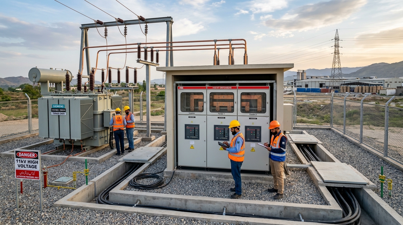
As industrial commercial enterprises across Pakistan—ranging from multi-acre textile spinning complexes in Faisalabad to cold storage hubs in Multan—install multi-megawatt on-grid solar photovoltaic systems, one engineering bottleneck consistently causes catastrophic generation loss: improper step-up transformer sizing and multi-inverter mismatch. Unlike conventional distribution transformers operating with passive linear loads, a solar inverter-duty transformer functions in continuous reverse power flow, subjected to high-frequency pulse-width modulation (PWM) harmonics, extreme ambient summer temperatures (exceeding 48°C), and non-isolated DC voltage offsets.
1. The Fundamental Physics of Solar Inverter Step-Up Transformers
In modern industrial solar arrays utilizing 100 kW to 330 kW string inverters (such as Huawei, Sungrow, or SMA), the AC output voltage generated at the inverter terminals is typically 800 V AC (3-phase, 3-wire) or 400 V / 415 V AC. To evacuate this generation into the factory's primary 11 kV or 33 kV medium-voltage distribution switchgear, a dedicated step-up transformer is mandatory.
Connecting high-capacity solar strings directly through existing factory distribution transformers leads to severe operational hazards:
- Excessive Core Saturation from DC Injection: Solid-state inverters occasionally inject small DC current components into the AC side during rapid irradiance transients. In standard distribution transformers, this DC offset shifts the core magnetic flux operating point, causing saturation, audible acoustic buzzing, and severe magnetic core losses.
- High-Order PWM Harmonic Heating: The high-speed IGBT switching frequencies (typically 2 kHz to 16 kHz) introduce 5th, 7th, 11th, and 13th harmonic currents. Standard transformers suffer excessive stray load losses in their structural clamps and tank walls.
- Inter-Inverter Circulating Currents: When multiple inverters share a single low-voltage busbar on an un-shielded transformer, differences in inverter carrier frequencies induce high circulating currents between inverters, causing unexpected tripping and thermal derating.
2. Mathematical kVA Sizing Formula for Multi-Inverter Installations
To accurately size a solar step-up transformer, engineers must calculate both the continuous apparent power demand ($S_{ ext{req}}$) and apply critical derating factors for high Pakistani ambient temperatures and harmonic content:
$$ ext{Transformer Sizing (kVA)} = rac{P_{ ext{solar\_peak\_ac}} ( ext{kW})}{ ext{Power Factor} imes K_{ ext{temp}} imes K_{ ext{harmonics}}} imes (1 + ext{Safety Margin})$$Where:
- $P_{ ext{solar\_peak\_ac}}$: Total cumulative continuous rated AC active power output from all connected solar inverters (kW).
- Power Factor ($\cos \phi$): Assumed at $0.95$ lagging to $1.00$ unity under typical active grid feed.
- $K_{ ext{temp}}$ (Ambient Temperature Derating Factor): In Punjab and Sindh where ambient summer temperatures exceed 45°C–50°C, transformer thermal dissipation derates capacity by $0.90$ to $0.92$.
- $K_{ ext{harmonics}}$ (Harmonic Factor): Set at $0.95$ for standard low THD (<3%) string inverters.
- Safety Margin: Standard engineering allowance of $10\%$ to $15\%$ ($1.10$–$1.15$) to prevent continuous 100% thermal stress during peak noon solar irradiance.
3. Single-Winding vs. Multi-Winding (Dual/Quad Secondary) Architectures
For installations exceeding 1 MW, the selection between a standard 2-winding transformer and a multi-winding split-secondary transformer represents the most critical architectural decision:
| Transformer Architecture | LV Inverter Inputs | Galvanic Isolation | Circulating Current Risk | Recommended System Size |
|---|---|---|---|---|
| Standard 2-Winding (Dyn11) | Single LV Bus | No (Common Bus) | Moderate | 300 kW to 630 kW |
| Dual Split-Secondary (Dy11y11) | Two Independent LV Windings | Full Isolation | Zero | 1,000 kW to 2,000 kW (1–2 MW) |
| Quad Split-Secondary (Dy11y11y11y11) | Four Independent LV Windings | Complete 4-Way Isolation | Zero | 2,500 kW to 5,000 kW (2.5–5 MW) |
4. Real-World Case Study: 1.2 MW Textile Spinning Solar Plant in Faisalabad
In 2025, a leading textile spinning mill in Khurrianwala, Faisalabad, installed a 1.2 MW rooftop solar array consisting of six 200 kW string inverters (800 V AC output). Initially connecting through a repurposed standard 1250 kVA distribution transformer, the mill experienced repeated overheating trips when ambient temperatures crossed 42°C in June.
TransfoLine Engineering Intervention:
- Replaced the generic unit with a custom-engineered TransfoLine 1500 kVA Dual-Secondary Split-Winding (0.8kV / 0.8kV to 11kV) Inverter-Duty Transformer.
- Integrated grounded copper electrostatic Faraday shields between each 800V winding and the 11kV high-voltage coil.
- Equipped the transformer with $K-9$ harmonic-rated copper conductors, magnetic oil level gauges (MOG), and automated ONAF cooling radiator fans.
- Result: Zero nuisance trips during 49°C ambient peak heat waves, full evacuation of 1.2 MW solar power, and annual energy export savings of PKR 68 Million.
5. Engineering Checklist for Solar Step-Up Substation Procurement
Before ordering an 11kV solar transformer in Pakistan, ensure your procurement specification mandates:
- 100% Pure Electrolytic Copper Windings: Aluminum coils exhibit higher temperature coefficients and fail prematurely under continuous heavy cyclic solar loads.
- Faraday Shielding: Continuous copper foil electrostatic shield grounded directly to the substation earth pit.
- Off-Circuit Tap Changer (OCTC): Standard $\pm 2 imes 2.5\%$ taps to adjust for seasonal DISCO 11kV grid voltage variations.
- Bi-Directional Protection Relay Coordination: Directional overcurrent (67/67N), anti-islanding (IEEE 1547), and reverse power relays calibrated for utility green meter compliance.
Need a Custom Solar Inverter Transformer Design?
Send your inverter string single-line diagram (SLD) to TransfoLine high-voltage engineers for an itemized sizing calculation and factory-direct wholesale quote in 2 hours.