
Why Standard Distribution Transformers Burn Out on Solar Inverter Duty
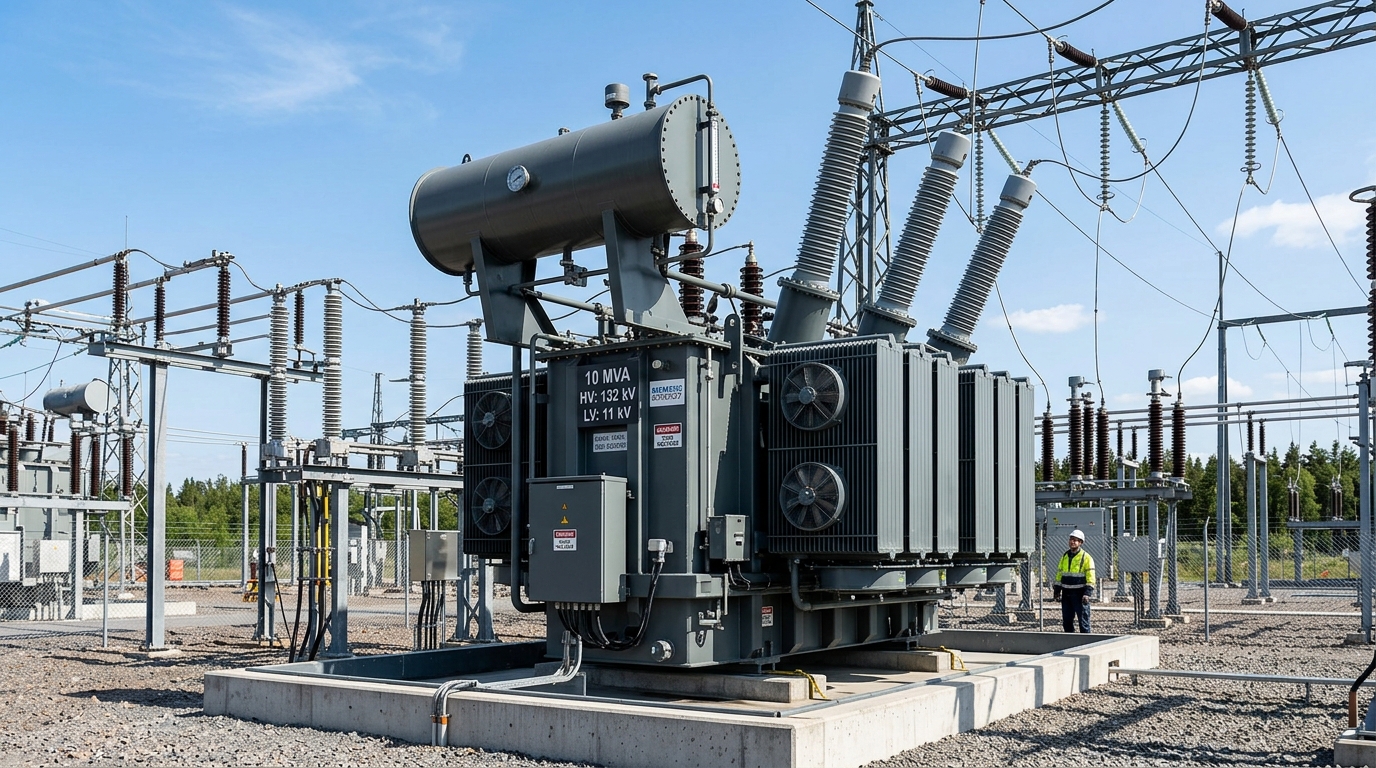
When commercial industrial companies in Pakistan install 500 kW to 2 MW solar plants, EPC contractors frequently attempt to reduce capital expenditures by utilizing standard off-the-shelf distribution transformers (WAPDA DDS-84 specification) to step up inverter voltages (400V/800V) to 11kV. Within 12 to 24 months of continuous operation, these generic transformers exhibit catastrophic failure: boiling dielectric oil, high concentrations of dissolved combustible gases (acetylene and ethylene), severely scorched insulation paper, and frequent differential relay trips. Understanding the fundamental electro-physical differences between distribution loads and solid-state inverter generation explains why specialized solar inverter-duty transformers are non-negotiable.
1. The Four Fatal Failure Mechanisms of Generic Transformers on Solar Duty
A. High-Frequency Harmonic Losses & Hot Spot Temperatures
Standard distribution transformers are designed for pure 50 Hz sinusoidal linear load currents. In contrast, grid-tied solar inverters synthesize AC waveforms using high-speed Insulated Gate Bipolar Transistors (IGBTs) switching at 2 kHz to 16 kHz.
Although inverter output chokes filter fundamental waveforms, significant high-order harmonic currents (3rd, 5th, 7th, 11th, and 13th orders) persist. These high-frequency harmonic currents dramatically elevate winding eddy current losses, which scale with the square of the harmonic order ($h^2$):
$$P_{ ext{eddy}} = P_{ ext{eddy\_fundamental}} imes \sum_{h=1}^{n} I_h^2 h^2$$In standard transformers with thick solid copper conductors, this causes localized thermal hot spots reaching 140°C–160°C, rapidly degrading cellulose paper insulation and cutting transformer lifespan from 30 years to under 3 years.
B. DC Voltage Bias & Half-Wave Core Saturation
During sudden solar irradiance fluctuations (e.g., passing monsoon clouds over Lahore or Faisalabad), string inverters can momentarily inject small DC current components ($I_{ ext{dc}}$) into the transformer low-voltage winding. In standard transformers, even a minute DC current offset of 0.1% of rated current causes half-cycle asymmetrical magnetic core saturation. This results in:
- Massive spikes in excitation current ($I_{ ext{exc}}$).
- Severe acoustic vibration and audible transformer humming.
- Rapid breakdown of transformer mineral oil, generating explosive methane ($CH_4$) and ethylene ($C_2H_4$) gases.
C. Absence of Electrostatic Faraday Shielding
When high-frequency switching transients occur on the solar inverter side, standard distribution transformers lack internal shielding. High-frequency common-mode voltage pulses couple directly across primary and secondary windings through inter-winding capacitance ($C_{ ext{ps}}$), stressing the 11kV insulation and causing flashovers across medium-voltage bushings.
D. Extreme Solar Thermal Cycling (Daily Expansion & Contraction)
Unlike continuous 24/7 factory loads, solar generation cycles violently from 0% load at night to 100%+ peak load at solar noon (coinciding with Pakistan's peak 48°C ambient summer temperatures). This severe daily thermal cycling accelerates gasket degradation, causes moisture breathing in standard conservators, and degrades oil dielectric breakdown voltage (BDV) below 30 kV.
2. Engineering Comparison: Solar Inverter-Duty vs. Distribution Transformer
| Engineering Parameter | Standard Distribution Unit (DDS-84) | TransfoLine Solar Inverter-Duty Unit |
|---|---|---|
| Harmonic Withstand | K-1 (Linear loads only) | K-9 / K-13 Harmonic Rated |
| Electrostatic Shielding | None (Direct capacitive coupling) | Grounded Copper Faraday Screen |
| Magnetic Core Flux Density | Standard 1.70 Tesla (Saturates on DC) | Conservative 1.55 Tesla (Anti-DC Bias) |
| LV Winding Design | Single Continuous Winding | Split-Secondary (Dual/Quad Isolated) |
| Insulation Class | Class A (105°C) | High-Temp Nomex / Class H (180°C) |
| Cooling System | ONAN Natural Convection | ONAF Automated Booster Radiator Fans |
3. How TransfoLine Engineers Protect Solar Investments
Every TransfoLine solar inverter-duty transformer incorporates three foundational engineering innovations:
- Continuously Transposed Conductors (CTC): By subdividing low-voltage copper coils into multiple insulated strands and transposing them throughout the winding, skin effect and high-frequency harmonic eddy losses are reduced by up to 60%.
- Electrostatic Faraday Shield: A pure copper foil screen placed between LV and HV coils intercepts common-mode inverter noise and channels high-frequency spikes directly to the earth pit before they stress medium-voltage insulation.
- Conservative Magnetic Core Cross-Section: Utilizing imported high-permeability, laser-scribed Grain Oriented Silicon Steel (CRGO) operating at low flux densities (<1.55T) guarantees that DC current offsets cannot push the transformer core into saturation.
Is Your Existing Solar Transformer Overheating?
Book an on-site thermal scan, dissolved gas analysis (DGA), and harmonic power quality audit from TransfoLine senior testing engineers.